EUREF-Czech-2009 campaign
by Jan Douša, Vratislav Filler, Jan Kostelecký, Jakub Kostelecký, Jaroslav Šimek
This report has been submitted for evaluation by the EUREF Technical Working Group in Gaevle, Sweeden, June 1, 2010. The full report is available in the proceedings of the EUREF symposium 2010.
1 Introduction
The reasons for ETRS89 implementation in the Czech Republic were threefold:
- Harmonization of the surveying and mapping legislation with IAG/CERCO/EuroGeographic and EC recommendations and directives
- Fostering the use of GPS technique and development of GPS based applications by a broad user community
- Improved realization of the classical national user geodetic reference system S-JTSK
The first expansion of the ETRS89 to the east was realized by the EUREF-CS/H’91 campaign in 1991. Eleven stations of the fundamental national geodetic network were observed by the former Institute of Applied Geodesy, Frankfurt am Main (present-day BKG) on the territories of Hungary (5 sites) and the former Czech and Slovak Federal Republic (6 sites). Only three of them (Pecný, Kleť, Přední příčka) are located on the territory of the Czech Republic and today none of them is operated as a permanent GNSS station with the exception of Pecný where the GOPE IGS/EPN station is located about 90 m apart. Note, that in processing of the EUREF-CS/H’91 campaign, which was performed in cooperation between BKG and RIGTC, no precise GPS orbits were available since it had been done in 1992 before a regular IGS operation started. Later, in 1993 the solution was slightly improved after the ideas by W. Gurtner and M. Rothacher by computing ad hoc “precise orbits” using several fiducial European permanent stations. This solution was validated by the EUREF TWG in 1994 as “class B”.
The Czech national user reference system (S-JTSK), which is one of the mandatory geodetic reference systems allowed in the Czech Republic and is used as a principal system for all legal mapping and surveying work, originates in 1927. Besides a wrong placing on the Bessel ellipsoid, wrong orientation and scale the realization of this system (first to fifth order national triangulation network) suffers from inhomogenities and many local deformations so that a large number of the triangulation points with ETRS89 coordinates regularly distributed over the entire territory is necessary to detect and rectify them. In 1992-1994, a sequence of campaigns was carried out to set up a national reference frame for the ETRS89 realization:
- CS-NULRAD (1992) – realization of the Zero-order network (6+13 stations) as a first densification of the frame set up by the EUREF-CS/H’91 campaign in the Czech and Slovak Federal Republic in 1991; processing done by RIGTC-GO Pecný using precise orbits kindly provided by Y. Bock of SIO.
- CS-BRD (1993) – the campaign to connect the GPS networks of the Czech Republic and Germany. Some of CS-NULRAD stations were re-observed, but finally the resulting accuracy of the re-processed coordinates was similar to that of the previous campaign; processing done by RIGTC-GO Pecný using precise IGS orbits.
- DOPNUL (1993-1994) – second order densification of the EUREF based reference frame on the territory of the Czech Republic stemming from the CS-NULRAD and CS-BRD campaigns and resulting in 176 stations (average distance of 25km) with both ETRS89 and S-JTSK coordinates; processing done by RIGTC-GO Pecný using IGS precise orbits.
The above mentioned campaigns represent a hierarchy of the sequential ETRS89 densification on the territory of the Czech Republic. The national CS-NULRAD and DOPNUL campaigns, which were based on the EUREF-CS/H’91 campaign, were not submitted to the EUREF TWG for validation. None of the stations is currently operated as a permanent GNSS station.
|
The active GNSS positioning system (CZEPOS), which was developed in the Czech Republic from 2004 to 2006, has been after an about one-year provisional operation fully operational since January 1, 2007. In 2008 and 2009, it was upgraded by implementation of the new stations, software tools and services. In April 2010, it consists of 54 permanent GPS/GNSS stations 27 of which are regularly distributed over the territory of the Czech Republic and the remaining 27 are located in the neighbour countries along the Czech border as a part of the national GNSS positioning systems of these countries. CZEPOS uses the data of these stations on the basis of bilateral agreements with their operators. Because the realization of ETRS89 coordinates in the Czech Republic comes from the early GNSS era, i.e. before the International GNSS Service (IGS) was established, the ETRS89 coordinates of CZEPOS stations were preliminary estimated from the first permanent GPS observations.
A new realization of the reference frame based on the ETRS89 coordinates of permanent GNSS stations in the Czech Republic is described in this report. This represents the first step for a further large scale densification represented by ETRS89 coordinates of about 46 500 points in the Czech Republic with an average distance of 2 km.
2 Campaign configuration
The EUREF-Czech-2009 campaign consists of available permanent GPS stations on the territory of the Czech Republic (44) and EPN stations in other European countries (18). The latter were selected using the following criteria:
- EPN Class A stations with defined coordinates and velocities.
- Station with smooth coordinate time-series in the EPN cumulative solution.
- Fiducial stations within the EPN cumulative solution.
- Location in the close surrounding of the Czech Republic.
- In distance to all directions from the middle of the network (approximately 1000 km).
|
The remote stations were included to minimize possible biases on the fiducial stations and to support the estimation of absolute values of tropospheric parameters.
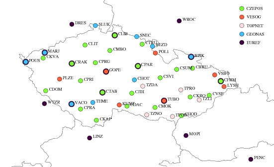
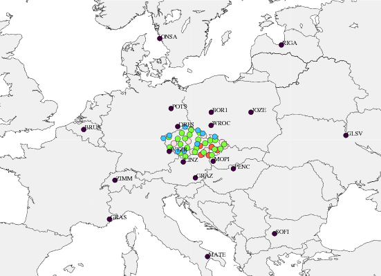
All Czech stations are plotted in Figure 1 and additionally introduced EPN stations in Figure 2. Only 8 from all the stations were processed for a period shorter than 3 years.
The station Sněžka (SNEC) is very well known for its problems during winter periods. The station is located on the top of the highest mountain in the Czech Republic which is well known for extremely severe weather conditions so that from early autumn till late spring its radome is usually covered with snow or, in worst case, even with a few centimetres of ice crust. The effects reached even more than decimetre in horizontal position, see e.g. EUREF CB web page coordinate time-series. For this reason, only data from snow-free periods (June-September, 2005-2009) were included in the daily processing. In 2009, the monumentation (an old building) was destroyed and the station was moved to another pillar. The reason why SNEC had to be included in the campaign was that the baselines using data from this station were observed and calculated in the past and will be probably necessary for selected local densifications.
Similar problems during winter periods can be seen in daily coordinate time-series of two other stations located at the top of high mountains in the region of Moravia – Lysá hora (LYSH) and Biskupská kupa (BISK). Nevertheless, the problems were significantly smaller and the data of winter periods were not excluded in daily processing, but only in the final combination if outliers were detected.
3 Daily processing
The processing was carried out using the Bernese GPS software V5.0 [Dach et al. 2007]. The strategy was based on the system developed at Geodetic Observatory Pecný (GOP) for the EUREF Permanent Network analysis. Only GPS data were used in the campaign, because only a few stations in the Czech Republic provide GPS+GLONASS observations and these are mostly equipped with problematic ASHTECH Z-18 receivers.
The main steps of the daily processing consist in:
3.1 Processing clusters
To complete data processing of 4 years within a few days a highly optimized processing scheme was prepared. This was achieved by splitting the network into clusters of a suitable size for parallel processing. Small clusters (4-8 stations) were designed for the ambiguity resolution and outlier rejection while large clusters (approximately 20 stations) usually for all others steps. Each processing step running in parallel ended with a combination, checking or summary extraction procedure.
3.2 A priori coordinates
A priori coordinates used in daily processing were prepared by merging the coordinates from three sources applied in a given order with an identification flag:
- Last IGS (or ITRF) realizations converted to the epoch of processed day using velocities consistent with coordinates
- Preliminary coordinates available from any previous solution (no velocities applied)
- Coordinates available in RINEX files (no velocities applied)
The coordinates were expressed in the epoch of processed day according to their velocities if available.
3.3 Orbits and Earth Rotation Parameters
Final IGS orbits and ERPs were fixed in the daily processing. The IGS final product is based on relative models of satellite and receiver antenna phase centre variations (PCV) before GPS week 1400 and on absolute PCV models starting with GPS week 1400. The absolute models were used in the campaign processing over the whole data span whereas the most important was to apply a consistent model for both satellite and receiver antennas. The satellites with zero accuracy codes (a few cases only) were a priori excluded from the processing. Nevertheless, our procedure independently checks residuals in order to identify any problematic satellite orbits.
3.4 Other external products and models
Applied models were consistent with the IERS 2003 conventions:
IGS final orbits and ERPs |
ftp://cddis.gsfc.nasa.gov/gps/products/www/igswwwd.sp3.Z ftp://cddis.gsfc.nasa.gov/gps/products/www/igswww7.erp.Z |
Ionospheric model |
ftp://ftp.unibe.ch/aiub/CODE/yyyy/CODwwwwd.ION.Z |
Antenna PCV |
ftp://ftp.epncb.oma.be/pub/general/epn_05.atx http://czepos.cuzk.cz/_paramAnten.aspx |
Ocean tide loading |
http://www.oso.chalmers.se/~loading/ (model FES2004, no CMC corrections) |
IGS05/ITRF2005 |
ftp://itrf.ensg.ign.fr/pub/itrf/itrf2005/ITRF2005.SNX.gz ftp://igscb.jpl.nasa.gov/pub/station/coord/IGS05.snx |
EPN cumulative solution |
ftp://epncb.oma.be/epncb/station/coord/EPN/EPN_A_ITRF2005.SSC (EPN_A_ITRF2005_C1570) |
3.5 Observation sampling, weighting and elevation cut-off angle
The 3 degree elevation cut-off angle was applied in all steps of the processing, but 10 degrees in the step for integer ambiguity resolution. By including low-elevation angle observations the estimation of horizontal troposphere gradients was supported (see Troposphere modelling). Observations with 30 sec sampling interval and the elevation dependent weighting function were used in pre-processing and 180 sec in final processing.
3.6 Ionosphere modelling
Wherever possible the first-order effect of the ionosphere was eliminated using ionosphere-free linear combination (single point positioning based on code observations, pre-processing for the cycle slip detection and outlier rejection and final modelling of the GPS observations for normal equation generation). The second- and third-order effects were neglected in the processing. While the estimation of the ionosphere model is also a part of our routine system, in this campaign the final CODE model was introduced to support the ambiguity resolution (see Ambiguity resolution).
3.7 Troposphere modelling
In pre-processing steps the troposphere effects were modelled with site-specific station parameters applying a simple tropospheric model and mapping function. In all steps requiring the highest accuracy of observation modelling, the following parameterization was applied (gradients were estimated only in the ambiguity-fixed solution):
- A priori model by Saastamoinen (1972), standard atmosphere and Niell dry mapping function (Niell, 1996). Loose constraints (5m) were applied for a priori values.
- Corrections estimated for each station and 60-min interval applying Niell wet mapping function (Niell, 1996). Loose relative constraints (1 m) were applied to subsequent values.
- Tropospheric horizontal gradients estimated for each station and 24-hour interval.
The troposphere parameters were pre-eliminated before saving daily normal equations. Thus, their connection at daily boundaries was not possible in the final combination. Whereas the effect on coordinate estimates in long-term combination is negligible, this approach significantly reduces requirements for the disk space and combination time.
3.8 Data cleaning
Detection of cycle-slips, removal of incomplete data and setting new ambiguities were done in several clusters using a triple-difference solution. Ambiguity-float solution was then used for post-fit residual screening and outlier detection. A problematic station or satellite could be detected during this step, followed by removal of all relevant data and jump back to the step of baseline definition. The last feature was practically not used in this processing campaign.
3.9 Datum definition
|
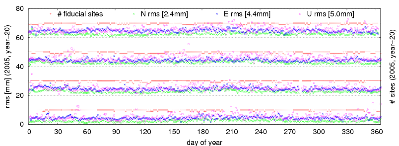
After data cleaning and outlier rejection, the daily combination of ambiguity-float solution was used for fiducial station selection. Stations used as fiducials in the IGS05 reference frame (BOR1, BRUS, GLSV, GRAS, JOZE, MATE, ONSA, POTS, WTZR, ZIMM) were used to define an initial set, while the selection procedure was based on a minimum constrained solution (NNT), which was repeated until the set of fiducial stations provided sufficiently small residuals. Only in a few cases in the whole period an additional iteration was used. The RMS of residuals for the fiducial stations were 2.4, 4.4 and 5.0 mm on average for North, East and Up, respectively. The RMS time-series are plotted in Figure 3.
3.10 Ambiguity fixing

|
The length of all baselines in the network was below 2000 km so that the QIF ambiguity resolution strategy (Mervart, 1996) could be generally applied. The ionospheric model was ready to be estimated within the campaign processing scheme, but finally this was not applied in order to minimize the time for a single day processing. The ionospheric product from the Centre of Orbit Determination in Europe (CODE) was introduced instead, which slightly increased the rate of fixed ambiguities by about 2-3% with respect to the estimated model. Apart from a priori ionosphere model, stochastic ionospheric parameters were estimated during the ambiguity fixing. The tropospheric parameters and a priori coordinates from daily ambiguity-float solution were introduced from the last iteration of the datum definition. The coordinates of one station were constrained for each cluster during the ambiguity resolution. On average 84% ambiguities were fixed. Figure 4 shows seasonal variation of the total number of fixed ambiguities per each day over the whole period.
3.11 Daily solutions
The final solution of daily processing consists of two steps:
- Correct correlation and modelling in 3-4 clusters (approx. 20 stations) with saving normal equations for each cluster
- Daily normal equation combination into a network solution (neglecting correlations across different clusters) and saving daily network normal equations
These normal equations from the network solution were input in the final 4-year combination. Nevertheless, thanks to well defined datum in daily solutions, we could directly plot daily coordinate differences with respect to simple mean values and immediately identify significant jumps and problems with daily solutions. Typical examples are given in Figure 5. Most of the coordinate differences are within ±1 cm with a standard deviation below 5 mm (including effects such as daily datum realization, antenna changes etc). All time-series are available at http://www.pecny.cz/EUREF-Czech-2009/DAILY-TIMESERIES.
4 Final combination
The Bernese ADDNEQ2 program was used for the final combination based on stacking daily normal equations (NEQ). Although the network spread over a stable part of Europe, coordinates and velocities were introduced as unknown parameters for this campaign covering the period of 4 years. The combination step consists in the identification of outliers and jumps, selection of fiducial stations and in setting pre-defined intervals for coordinate and velocity estimation. More different combination variants have been computed in order to achieve the best results. Because we introduced 24 EPN stations of Class A (6 in the Czech Republic and 18 external) in daily solutions, we didn’t need to combine NEQs with EPN weekly solutions. This was confirmed by a stable realization of the IGS05 reference frame on a daily basis, which was visualized in the preliminary time-series of coordinate differences with respect to a simple mean from independent days, see http://www.pecny.cz/EUREF-Czech-2009/DAILY-TIMESERIES.
.
4.1 Fiducial stations
Sufficient number of EPN Class A station candidates was available for the campaign and the selection of the most reliable set resulted in these different variants (full station lists are given in Table 3):
- A) 11 EPN (Class A) stations used as fiducial in the EPN cumulative solution
- B) 10 IGS/EUREF (Class A) stations used in IGS05 realization (applied in daily solutions)
- C) All EPN (Class A) stations with GOPE excluded before GPS week 1400 (24 stations)
- D) All EPN (Class A) stations with excluded intervals with larger residuals (23 stations)
4.2 Reference coordinates and velocities
The coordinates and velocities from the EPN cumulative solution EPN_A_ITRF2005_C1570 were used as a reference for all fiducial stations. During the campaign period, several sets of coordinates were published for most of the stations included in the campaign. These are usually related to the change of antenna or receiver. However, there are many coordinate changes at GPS week 1400, which are related to the changes in the EPN processing strategy – the most important was a switch from the relative to absolute phase centre model. For many stations, this caused a station-specific change in coordinates at a level of millimetres for horizontal position and centimetres in height.
The campaign covered the period both before and after GPS week 1400, while the absolute phase centre variation model was applied for the whole campaign processing period. Since the coordinates in the EPN cumulative solution before GPS week 1400 are based only on the processing that use relative phase centre variation model, we clearly identified jumps in our preliminary coordinates induced by this model change. These artificial jumps were eliminated in our campaign by omitting those sets of EPN coordinates with a time span limited only to a period before GPS week 1400. Instead, the coordinates starting at GPS week 1400 were used also for such station for the period without any instrumentation change. A consistency of the coordinates was thus guaranteed as long as possible also before GPS week 1400 and reference coordinates from the old model were used only in a few short periods at the beginning for these stations – DRES, GOPE, PENC, RIGA, TUBO and WROC.
A priori coordinates of all non-EUREF campaign stations could be set up at a decimetre level. Since the campaign covered 4-year period and the processing has been done in a global reference frame, velocities should be estimated as well. For a few stations we tightly constrained these velocities to their a priori values (because of short-time observed period), therefore we set their a priori velocities consistently with the rotation of ETRF2000 with respect to ITRF2005.
4.3 Outlier rejection
The final combination was done in an iterative way in order to eliminate outliers. The following criteria were used for the outlier detection:
- 8, 8 and 25 mm in North, East and Up for all EPN sites
- 15, 15 and 40 mm in North, East and Up for all other stations
The number of excluded days in final combination due to these criteria was 182 and 62 on fiducial and other stations, respectively.
| Site | From | To | Length (days) | Problem | JOZE | 2005 12 01 | 2006 02 28 | 424 | systematic outliers | BISK | 2005 11 20 | 2006 03 10 | 110 | winter outliers | BISK | 2007 12 12 | 2007 12 23 | 12 | series of Up outliers | LYSH | 2005 10 15 | 2005 10 25 | 11 | winter 2005/6, part 1 | LYSH | 2005 11 01 | 2006 04 15 | 165 | winter 2005/6, part 2 | LYSH | 2006 10 15 | 2007 03 20 | 156 | winter 2006/7 | LYSH | 2007 10 10 | 2008 02 20 | 133 | winter 2007/8 | SNEC | Oct- | -May | ~60% | all winter periods excluded in daily solutions | KUNZ | 2006 01 01 | 2006 03 07 | 66 | winter 2005/6 |
4.4 Coordinate and velocity estimation
The coordinates of all stations were estimated in pre-defined intervals according to the jumps identified from residual time-series. Sets of fiducial stations were used for the datum definition using the minimum constrained solution (no-net translation). The velocities were estimated only for all non-EUREF stations observed over 3 years. Since a priori velocities for such stations originated from a common ETRF2000 trend, we estimated corrections only and whenever more intervals for station coordinates were pre-defined, these corrections were estimated uniquely over the whole interval (there was no reason for splitting velocities during the campaign period).
In variants A, B and C, we have estimated only horizontal velocities in all variants, while vertical velocities were tightly constrained to their a priori values. In variant D, vertical velocities were also estimated for all stations observed over more than 3 years. The reference velocities of all EPN stations were always tightly constrained since we assumed that they could not be estimated with a higher quality than in the EPN cumulative solution.
5 Campaign Results
| Variant | Translations [mm] (all "Class A" sites) |
Translations [mm] (selected fiducal sites only) |
RMS [mm] of Helmert transformation (selected fiducal sites only) |
|||||||
| North | East | Up | North | East | Up | North | East | Up | Total | |
| A | -0.0 | -0.9 | -0.5 | +0.1 | -0.1 | -0.0 | 1.0 | 0.8 | 3.5 | 2.1 |
| B | -0.0 | -0.9 | -0.6 | +0.1 | -0.1 | -0.0 | 1.0 | 0.8 | 3.6 | 2.2 |
| C | +0.3 | -0.1 | -0.9 | +0.1 | -0.1 | -0.1 | 1.1 | 2.1 | 3.2 | 2.3 |
| D | +0.4 | -0.4 | -1.3 | +0.1 | -0.1 | -0.0 | 1.1 | 1.2 | 2.5 | 1.7 |
|
3D Helmert transformation (translation estimates) was performed for all the combination variants in order to assess the closeness of resulting coordinates to the ETRS89 realization (EPN cumulative product). The estimated translations for each variant using all class ‘A’ stations are within 1.3 mm in East, North and Up component, see Table 2. This result proved that any selection of ten or more fiducial stations in the campaign is reliable for the realization of the ETRS89 reference system at a millimetre level.
|
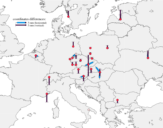
The table further shows fulfilled NNT conditions and RMS from coordinate residuals of applied fiducial stations. The solution ‘D’ shows clearly a superior performance while total RMS of Helmert transformation decreased to 1.7 mm. The solution ‘D’ was selected as final also because it includes as many as fiducial stations and excluding only three stations (MATE, and partly GOPE, WROC) with residuals larger than 6 mm in any component. Besides the station selection, Table 3 summarizes residuals from the final solution D and Figure 6 plots their geographical distribution.
|
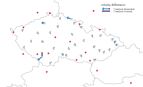
Estimated coordinates and velocities in ITRF2005 and ETRF2000 reference frames are summarized in Appendix. Figure 5 visualizes velocity corrections from the final solution (D) with respect to a priori velocities. Velocity differences are very small (bellow 1mm/year) for all stations, but for SNEC and CPRA.
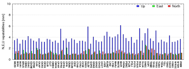
Repeatabilities for all stations were calculated for each variant, but they do not differ significantly – 2mm in horizontal component (only SNEC slightly more) and usually 4 mm in vertical (with a few stations up to 6 mm). Figure 7 shows repeatabilities for final solution (D).
The examples of coordinate time-series from the final combination are given in Figure 9 for three stations – one fiducial (POTS) and two CZEPOS stations (CPAR, CJIH). While CPAR is an example of an excellent performance, CJIH suffers from a seasonal effect probably due to steel mast monumentation. A similar but smaller effect was detected at some other CZEPOS stations with the same type. The time-series of all other stations can be found at http://www.pecny.cz/EUREF-Czech-2009/FINAL-TIMESERIES.
| Station | Fiducial set | D - final solution | ||||||
| A | B | C | D | North [mm] | East [mm] | Up [mm] | Flag | |
| BISK 11520M001 | x | x | 0.2 | 0.8 | 0.6 | |||
| BOR1 12205M002B | x | x | x | x | -0.3 | -0.5 | 0.4 | |
| BRUS 13101M004B | x | x | x | x | -0.7 | 1.7 | -1.2 | |
| DRES 14108M001 | x | x | -1.3 | -2.1 | -2.3 | |||
| DRES 14108M001C | x | x | -1.2 | -1.7 | -1.3 | |||
| DRES 14108M001D | x | 2.2 | 0.0 | 6.7 | M | |||
| GLSV 12356M001B | x | x | x | x | 2.3 | -0.3 | 2.5 | |
| GLSV 12356M001C | x | x | x | x | 1.2 | 0.0 | 3.6 | |
| GOPE 11502M002 | 3.2 | -1.4 | -17.2 | M | ||||
| GOPE 11502M002B | 2.7 | -1.1 | -20.3 | M | ||||
| GOPE 11502M002C | x | x | 0.1 | 0.1 | 0.7 | |||
| GRAS 10002M006B | x | x | x | x | 0.2 | 1.3 | -4.1 | |
| GRAZ 11001M002 | x | x | 0.3 | 0.1 | -1.1 | |||
| GRAZ 11001M002B | x | x | -0.7 | -2.1 | -2.5 | |||
| GRAZ 11001M002D | x | x | 0.0 | 1.0 | -1.5 | |||
| JOZE 12204M001B | x | x | x | x | 0.0 | -0.2 | 1.3 | |
| LINZ 11033S001B | x | x | 0.1 | 1.0 | -2.0 | |||
| MARJ 11517M001B | x | x | 0.2 | 1.0 | 0.4 | |||
| MATE 12734M008B | x | x | x | 2.4 | 0.8 | -6.5 | M | |
| MATE 12734M008C | x | x | x | 0.4 | 1.5 | -7.1 | M | |
| MOPI 11507M001B | x | x | 0.1 | 0.3 | -1.9 | |||
| ONSA 10402M004B | x | x | x | x | -0.7 | -0.1 | 2.8 | |
| PENC 11206M006 | x | x | -3.6 | -0.2 | -0.2 | |||
| PENC 11206M006B | x | x | 0.2 | 0.4 | 1.7 | |||
| PENC 11206M006C | x | x | 3.0 | -2.3 | -1.9 | |||
| POTS 14106M003 | x | x | x | x | -0.3 | 0.3 | 2.3 | |
| POUS 11518M001 | x | x | -0.1 | 1.2 | 0.1 | |||
| RIGA 12302M002 | x | x | -0.4 | -1.0 | 1.9 | |||
| RIGA 12302M002B | x | x | -0.6 | -1.0 | 2.5 | |||
| RIGA 12302M002C | x | x | 0.3 | -0.6 | 4.6 | |||
| SOFI 11101M002 | x | x | x | 0.4 | 0.3 | -1.5 | ||
| TUBO 11503M001 | x | x | -0.8 | -2.1 | -2.7 | |||
| TUBO 11503M001B | x | x | 1.4 | 3.0 | -5.7 | |||
| TUBO 11503M001D | x | x | -0.3 | -1.0 | 4.6 | |||
| VACO 11516M001B | x | x | 0.7 | 0.4 | 1.5 | |||
| WROC 12217M001 | x | 0.3 | -0.5 | -6.3 | M | |||
| WROC 12217M001C | -0.8 | -10.9 | -0.9 | M | ||||
| WROC 12217M001D | x | x | -0.2 | -0.4 | 0.7 | |||
| WTZR 14201M010B | x | x | x | x | 0.3 | 1.1 | 1.3 | |
| ZIMM 14001M004B | x | x | x | x | 0.2 | 0.7 | -3.8 | |
| RMS / comp. | x | 1.1 | 1.2 | 2.5 | ||||
| Translations | x | 0.1 | -0.1 | 0.0 | ||||
6 Transformation to ETRS89
The final combination was calculated in the International Terrestrial Reference System (ITRS), which requires velocities to express coordinates in different epochs. Resulting coordinates from our combination had to be transformed into the European Terrestrial Reference System (ETRS89) in order to minimize coordinate changes in time. The latest ETRS89 realization based on ITRF2005 is maintained via the cumulative EPN solution (Kenyeres, 2009).
In transformation we followed the procedure described in Memo (Boucher and Altamimi, 2008) using two approaches to transform ITRF2005 coordinates and velocities into the ETRF2000:
- a) Two-step transformation: ITRF2005 ⇒ ITRF2000 ⇒ ETRF2000
- b) Direct transformation ITRF2005 ⇒ ETRF2000 using 14-element transformation (three translations, three rotations and scale in basic epoch and their time changes)
Both transformations approaches agrees on submilimetre level and the difference is caused by rounding errors when reproducing coefficients directly from the Memo. The coefficients are more accurately given at http://itrf.ensg.ign.fr/ITRF_solutions/2005/tp_05-00.php. The EPN web-page service (http://epncb.oma.be/_dataproducts/coord_trans), which are using those more accurate coefficients, was finally used in the transformation.
7 Comparison with previous realization
This comparison evaluates the quality of older campaigns that contributed to the previous ETRS89 realisations in the Czech Republic than the quality of this campaign. However it is important to consider the discontinuity between previous and current national ETRS89 realisations.
The previous realisation of ETRS89 is described in Section 1. As a result, there exists a set of ETRS89 coordinates for 27 actually processed sites of the CZEPOS network in previous realisation. Table 9 shows translations and RMS errors estimated from Helmert transformation.
Nearly 1 cm offset in the North component is remarkable. Except that, the comparison shows a good agreement on a centimetre level in horizontal direction and a few centimetres in height. Only one station (CPRA) shows more than 15 mm difference in horizontal direction and two stations (CPRG and CMBO) exceed 30 mm in vertical direction.
| Number of sites | Translations | RMS of Helmert transformation | ||||||||||||
| North [mm] | East [mm] | Up [mm] | North [mm] | East [mm] | Up [mm] | Total [mm] | ||||||||
| 27 | 9.9 | -1.7 | 1.1 | 5.3 | 6.5 | 15.6 | 10.2 | |||||||
8 Conclusions
Altogether 44 Czech national and 18 EPN stations located in other European countries were processed during 4-year campaign and combined coordinates were converted into ETRF2000. For most of the stations 4-year observation time-series were considered, for some shorter time series, but minimally of 1 year. Data from winter periods were excluded for SNEC and LYSH stations located on the top of high mountains.
A high internal consistency of the campaign solution during the whole period is demonstrated by daily coordinate repeatabilities for all stations with a maximum of 2, 2 and 6 mm in North, East and Up component, respectively.
Four variants were tested differing in fiducial station configuration and coordinate and velocities parameterization. No significant difference between the realizations of the ETRS89 was found since all of them agreed within 1.3 mm in three translations.
Finally, 23 fiducial stations were selected for the final realization using a minimum constrained solution (no-net translation) with respect to the EPN cumulative solution (EPN_A_ITRF2005_C1570). Residuals on the fiducial stations demonstrate the consistency of estimated coordinates with ETRS89 at the level of 1.7 mm in total RMS from Helmert transformation and 1.1, 1.2 and 2.5 mm for North, East and Up component, respectively.
An indirect comparison with the previous ETRS89 realization in the Czech Republic could only be applied using coordinates derived in roundabout multi-step approach for all CZEPOS stations (see description of previous realization of ETRS in the Czech Republic in Section 1). The total RMS from the Helmert transformation for 27 stations is 10.2 mm (in 2007.0), while estimated translation parameters were 9.9, -1.7 and 1.1 mm for North, East and Up components, respectively.
The EUREF Technical Working Group was asked to validate the coordinates (not velocities) resulting from this campaign. The campaign was validated at the EUREF TWG meeting on June 1st, 2010, in Gaevle, Sweeden, which was confirmed by resolution No. 1 from the EUREF Symposium 2010 at the same place.
Ackwnoledgements
The data and products used in the EUREF-Czech-2009 campaign processing were kindly provided by the following organizations:
- data and products from the EUREF Permanent network (EPN) http://epncb.oma.be/
- orbit and clock products from the International GNSS Service (IGS) http://igscb.jpl.nasa.gov/
- data from CZEPOS operated by the Land Survey Office (LSO) http://czepos.cuzk.cz/
- data from VESOG network operated by the Research Institute of Geodesy, Topography and Cartography in collaboration with University of West Bohemia in Plzeň, Brno University of Technology, VŠB Technical University of Ostrava and Military Geographical and Hydrometeorological Institute http://oko.asu.cas.cz/vesog/
- data from GEONAS network operated by the Institute of Rock Structure and Mechanics, Academy of Sciences of the Czech Republic http://www.geonas.irsm.cas.cz/
- data from TOPNET network operated by GEODIS, s.r.o. company http://www.geodis.cz/produkty/topnet
All these contributions are gratefully acknowledged.
References
- Bruyninx, C., Altamimi, Z., Caporali, A., Kenyeres, A., Lidberg, M., Stangl, G., Torress, G.A. (2009), Guidelines for EUREF Densifications, Version 1: 26-05-2009, ftp://epncb.oma.be/pub/general/Guidelines_for_EUREF_Densifications.pdf
- Boucher, C., Altamimi, Z. (2008), Memo: Specification for reference frame fixing in the analysis of EUREF GPS campaigns. Version 7, http://etrs89.ensg.ign.fr/memo-V7.pdf
- Dach, R., Hugentobler, U., Fridez, P., Meindl, M. (eds.) (2007), Bernese GPS software V5.0, Astronomical Institute, University of Bern, Switzerland
- DeMets, Ch., Gordon, R.G., Argus, D.F., Stein, S. (1994), Effect of recent revisions to the geomagnetic reversal time scale on estimates of current plate motions, Geophysical Research Letters, Vol 21, No 20, pp. 2191-2194
- IERS Conventions (2003), McCarthy, D., Petit, G. (IERS Technical Note, 32) Frankfurt am Main: Verlag des Bundesamts für Kartographie und Geodäsie, 2004, 127 pp. http://www.iers.org/IERS/EN/Publications/TechnicalNotes/tn32.html
- Kenyeres, A. (2009), Maintenance of the EPN ETRS89 coordinates, presented at the EUREF TWG Spring Meeting, Feb. 26-27, 2009, Budapest, available from http://www.euref.eu/TWG/EUREF%20TWG%20minutes/49-Budapest2009/03-e-ETRSmaint_TWGrepBP.pdf
- Mervart, L. (1995), Ambiguity Resolution Techniques in Geodetic and Geodynamic Application of the Global Positioning System, Ph.D. Thesis, Astronomical Institute, University of Bern
- Saastamoinen, J. (1972), Atmospheric correction for the troposphere and stratosphere in radio ranging of satellites, In The Use of Artificial Satellites for Geodesy, Geophys. Monogr. Ser., vol. 15, Henriksen, S.W., Mancini, A., Chovitz ,B.H. (eds.), pp. 247-251, AGU, Washington, D.C.
- Niell, A.E. (1996), Global mapping functions for the atmosphere delay at radio wavelengths, JGR, 100, pp.3227–3246